Blog
As-Built Layouts
Block diagrams and as-built diagrams are essential engineering documents used in the design, implementation, and maintenance of Radio Frequency (RF) communication systems. While a block diagram represents the logical and functional architecture of a system, an as-built diagram reflects the actual configuration and connections after installation.
Together, they provide a complete visual and technical understanding of how the system is structured, operates, and integrates with other components such as power, IP, and RF subsystems.
Block Diagrams
A block diagram is a simplified graphical representation of the functional relationships between major system components. It focuses on signal flow, logical interconnections, and system hierarchy, rather than detailed wiring or physical layout.
In RF projects such as TETRA base station deployments, in-building coverage systems, or tunnel communication networks, block diagrams are used during the design and planning phase to visualize how RF, electrical, and IP subsystems interact.
Purpose of Block Diagrams
Block diagrams are developed to:
- Define system architecture and major equipment roles (e.g., base stations, combiners, repeaters, antennas).
- Illustrate signal flow from source to destination (TX and RX paths).
- Show interfaces between RF, power, and data systems.
- Provide a clear overview for design review and technical approvals.
- Serve as a reference for detailed wiring and layout design.
Typical Components in RF Block Diagrams
- TETRA Base Station (TBS)
- Combiner
- Duplexer / Filter
- Power Amplifier (PA)
- Antenna System
- Rectifier and Power Distribution Units (PDU)
- Network Management and Control System (via IP links)
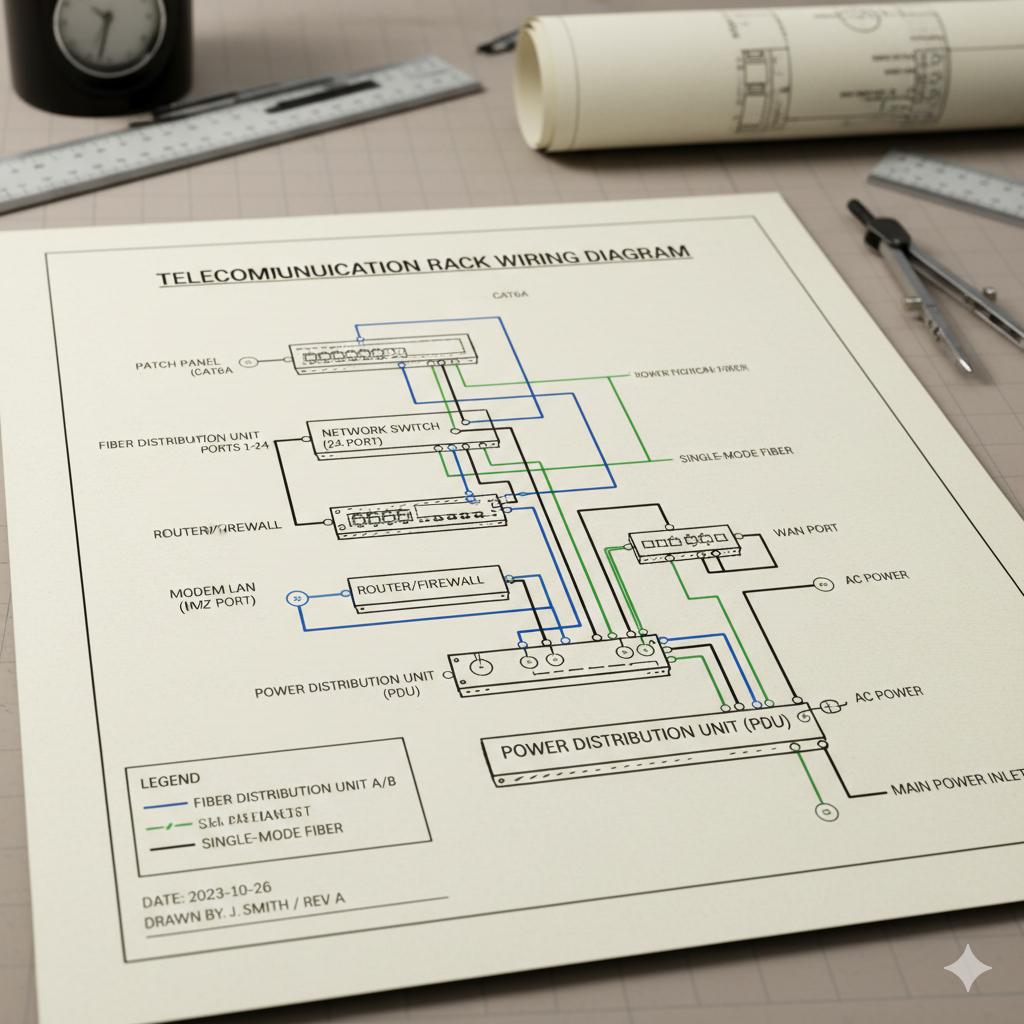
Each block is labeled with its function, input/output ports, and relevant signal direction. Lines connecting blocks represent RF paths, IP communication links, or power lines, often differentiated by color or line style.
As-Built Diagrams
An as-built diagram represents the final, installed configuration of the system after construction, integration, and testing are complete.
While block diagrams are conceptual, as-built diagrams are factual and field-verified, showing the actual equipment layout, cabling, labeling, grounding, and interconnections used on-site.
Purpose of As-Built Diagrams
- Document the exact system configuration after project completion.
- Reflect any changes or deviations from the original design.
- Provide a reliable reference for maintenance, troubleshooting, and future upgrades.
- Verify compliance with engineering standards and customer specifications.
- Serve as official documentation for handover and acceptance testing.
Typical Information Included
- Equipment part numbers, serial numbers, and installation locations.
- Cable types, lengths, labels, and connector references.
- Grounding and bonding details.
- IP addresses, VLAN information, and port assignments (for networked systems).
- Reference to rack layouts and antenna positioning.
Importance in RF System Lifecycle
Both block and as-built diagrams are vital throughout the RF system lifecycle:
| Project Phase | Diagram Type | Purpose |
| Design & Planning | Block Diagram | Defines the logical and functional architecture. |
| Installation & Commissioning | Wiring Diagram | Guides physical interconnection of components. |
| Post-Installation / Handover | As-Built Diagram | Documents the verified final configuration. |
Maintaining accurate and updated diagrams ensures consistency, traceability, and ease of troubleshooting across all stages of system operation. For mission-critical networks such as TETRA, this documentation directly contributes to network reliability, safety, and service continuity.