Blog
Wiring and Layouts
Wiring diagrams and layouts play a crucial role in the design, installation, and maintenance of Radio Frequency (RF) systems. especially in mission-critical networks such as TETRA and Private Mobile Radio (PMR) systems. These diagrams provide a complete visual representation of how RF, electrical (power), and IP (data) connections are integrated within a communication infrastructure. They serve as a blueprint for engineers and technicians to understand signal flow, equipment interconnections, and system topology, ensuring that the installation is accurate, safe, and aligned with design specifications.
Purpose of Diagrams
The primary purpose of a wiring and layout diagram are to illustrate how all system components are interconnected, including their signal paths, power sources, and data links. In a professional RF project, a comprehensive diagram enables engineers to:
- Visualize the end-to-end signal flow for both transmit and receive paths.
- Identify and label RF cables, power supply lines, and Ethernet or fiber connections.
- Verify equipment grounding, isolation, and shielding practices to prevent interference or electrical faults.
- Ensure impedance matching and proper terminations to maintain optimal RF performance.
- Facilitate system integration, testing, and troubleshooting during installation and maintenance phases.
- Provide clear documentation for future expansion or upgrades
Typical Elements in RF System Diagrams
A complete RF system diagram typically includes three major categories of connections:
RF Wiring
- Components: Base station transceivers, duplexers, combiners, filters, splitters, couplers, and antennas.
- Cabling: Coaxial feeders, RF jumpers, and leaky feeder cables for tunnels or underground areas.
- Labels: Frequency bands, port names, and signal direction (TX/RX).
Electrical Wiring
- Components: Power distribution units (PDUs), circuit breakers, rectifiers, and backup power systems (UPS or batteries).
- Cabling: AC and DC power lines, grounding conductors, and bonding points.
- Purpose: To ensure stable power supply, equipment protection, and proper grounding for safety and EMI reduction.
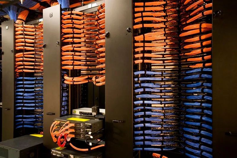
IP/Data Wiring
- Components: Routers, switches, network management systems, and dispatch consoles.
- Cabling: Ethernet (Cat6/Cat7), fiber optic lines, and patch panels.
- Purpose: To connect base stations, controllers, and operation centers for voice, data, and signaling exchange.
Importance in RF Network Integration
In integrated communication systems such as metro tunnels, airports, or industrial plants, the combination of RF, power, and IP wiring ensures reliable system operation. Proper wiring diagrams help coordinate multidisciplinary teams (RF, electrical, and IT engineers) by providing a unified view of the entire network infrastructure. These diagrams are essential during all project stages, including design review, factory acceptance testing, installation, commissioning, and maintenance. A well-prepared wiring diagram ultimately guarantees network reliability, service continuity, and operational safety.